Interference Management: integrated BIM-MEP design
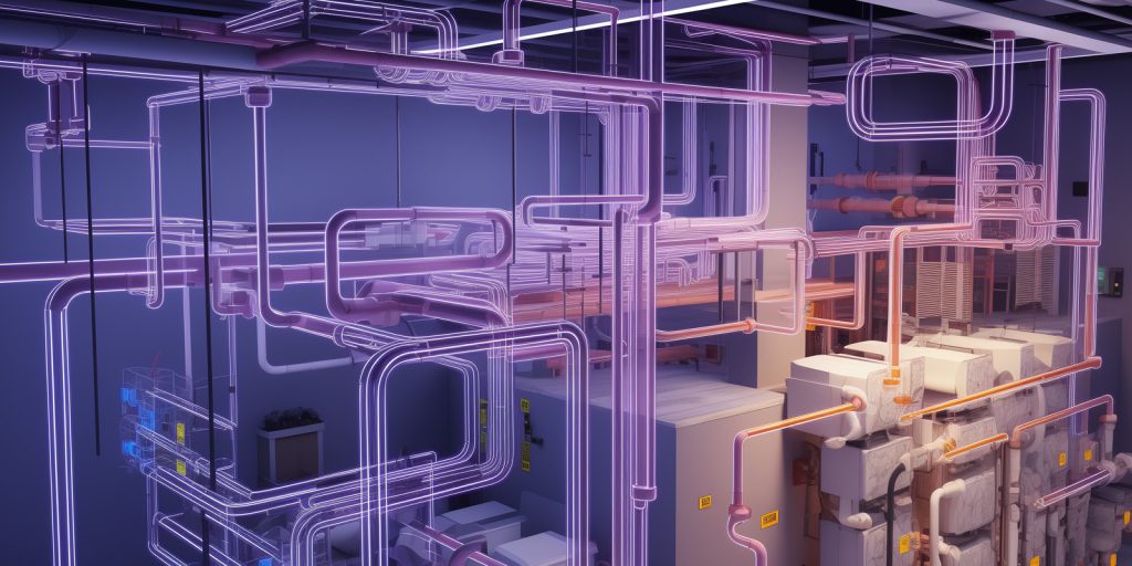
Interference management is an aspect that involves all phases leading to the completion of a project, from the design phase to the execution phase. Managing interferences is not easy, especially when the project to be designed and realized involves many aspects, such as architectural, mechanical, electrical, and plumbing (MEP), and structural components. Possible interferences in the design phase To avoid errors due to interferences between these parts, it is important to rely on working tools such as BIM, which allow simultaneous work on the various components of the project and have the right comparisons already in the design phase. As already mentioned, the first interferences between design sectors manifest themselves in the initial design phase. The most common examples of interferences and conflicts that can occur between MEP and architectural components are as follows: space problems for the placement of systems; structural conflicts resulting from inadequate coordination. Integrated BIM – MEP design for interference management Resolving interferences in the design phase is crucial to avoid additional costs and delays in project completion. For this reason, it is important to rely on integrated design tools such as BIM – MEP, which allow optimal coordination between the various components involved in construction and data sharing among professional figures. Therefore, BIM – MEP design allows for complete coordination during the construction process, anticipating and resolving many issues and conflicts already in the design phase. The shared use of models allows for active management of interferences between systems and architectural and structural models, identifying and resolving system interferences even before they translate into execution problems. The benefits of integrated BIM-MEP Design The primary benefits of BIM-MEP design include: 3D development of the design. Integrated and interdisciplinary design facilitating collaboration and data sharing among various professional figures involved. Management of interferences between systems and the architectural and structural model. Rapid processing of projects. Ease of making changes to projects. Increased precision in evaluations. Reduced likelihood of errors and issues on-site. Accurate control over project timelines and costs. Improved clarity in communicating project decisions. Streamlined management even during the maintenance phase. Practical example of managing interferences between architectural and MEP projects The images below show an interference between architectural and MEP (Mechanical, Electrical, and Plumbing) projects. In particular, images 1 and 2 depict two design phases of the VRF (Variant Refrigerant Flow) system. Image 1 concerns the final design phase of the VRF system; in this phase, the elevator system, previously nonexistent, was incorporated. As evident from the image, the passage of VRF system piping interfered with the elevator shaft. The designers identified the interference through the integrated working method and found a solution already in the design phase (see image 2).
Plant refunctionalization project for a municipal building – Osasio
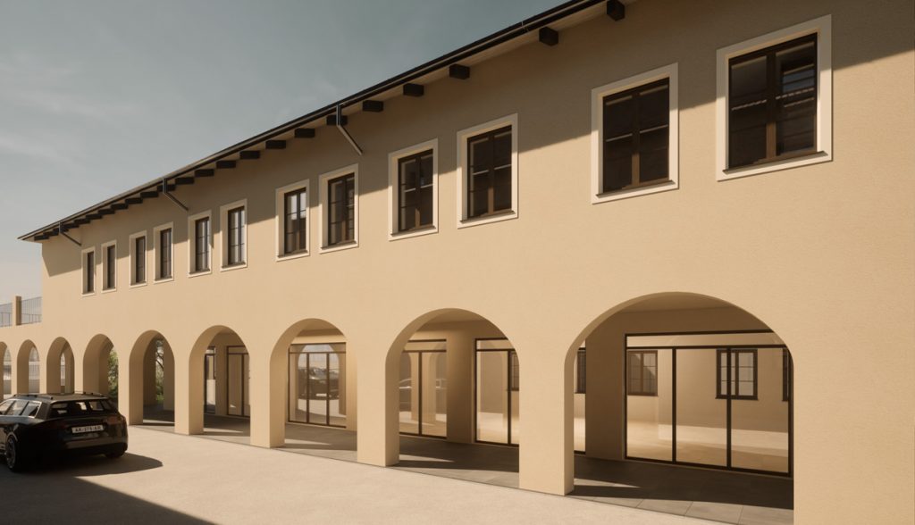
The innovative social housing project, conceived and realized by Orbyta Engineering, has breathed new life into a municipal building, transforming it into a facility dedicated to the well-being of self-sufficient elderly individuals. An operation that goes beyond architectural refurbishment, including an advanced approach to plant design to ensure a sustainable and comfortable environment. Plant design The building, spread over two above-ground floors, has been designed to accommodate various activities. The ground floor will host medical offices, while the upper floor will be entirely dedicated to social housing for self-sufficient elderly individuals. VRF system A key element of this design is the Variable Refrigerant Flow (VRF) system, characterized by an outdoor motor-condensing unit controlled by an inverter and a number of indoor units installed at floor level, ensuring high energy efficiency. This system not only allows for precise control of indoor temperature and humidity but also significantly contributes to environmental sustainability. VMC system The presence of a Mechanical Controlled Ventilation (MCV) system on both floors, for both the medical offices on the ground floor and the Social Housing on the upper floor, promotes continuous air exchange and environmental purification. The integration of heat recovery units optimizes energy efficiency, ensuring high standards of comfort and healthiness. Underfloor heating system and drainage system The use of a radiant underfloor heating system, supported by an air-water heat pump and insulating panels, ensures uniform and efficient heat distribution. The drainage system, designed in accordance with current regulations, includes pipes sized according to flow rate and a pumping station for wastewater lifting. Photovoltaic panel system The implementation of a 15 kW photovoltaic system, located on the building’s roof, represents a milestone in promoting energy sustainability, allowing for solar energy production. To learn more about the energy efficiency project carried out, check out our Portfolio. Underfloor heating system Photovoltaic panel system VMC system